Search filter
Filter
Reset- Installation drawing (778)
- Product data sheet (756)
- Installation instructions (220)
- Tender texts (177)
- Product scale drawing (110)
- 3D model (89)
- Certificate (82)
- Declarations of performance (79)
- Declaration of conformity (63)
- Cable plan (57)
- Wiring diagram (36)
- Environmental declaration (32)
- User manual (29)
- Supplementary sheet (19)
- Flyer/folder (16)
- Product brochure (16)
- Declaration of incorporation (15)
- Inspection certificate (8)
- T&C / Data Protection (5)
- Type examination certificate (4)
- Software (3)
- Supplier information (3)
- Evaluation/comment (1)
- Customer information (1)
2599 results found
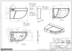
Hold-open magnet International 230V
(DWG | 420 KB)
Magnetic counterplate with joint
(DWG | 101 KB)
Installation drawing Hold-open magnet Wall installation 65mm
(DOCUMENT | 262 KB)
1 … Magnetsensor zum Testen (hinter GEZE Logo) LED zur Zustandsanzeige Anschluß an Sturzrauchschalter GC 151 XX Jumper J2 (rot) abziehen (= mit Deckenmelder). XX Jumper J3 zur Messkammer hin setzen (Pin 2-3, = mit Leitungsüberwachung). XX Widerstände im Sockel des ersten Deckenmelders trennen . XX Kabeltyp J-Y(ST)Y, 2x2x0,6 mm2 oder 2x2x0,8 mm2 verwenden. Länge maximal 15m. Klemmdose GC 152 DE Deckenrauchmelder GB Ceiling smoke detector GEZE GmbH Reinhold-Vöster-Straße 21–29 71229 Leonberg Germany Verwendung Der GC 152 ist ein Deckenrauchmelder zur Verwendung in der GEZE Feststellanlage FA GC 150. Rauchmelder erkennen Rauch. Sie arbeiten nach dem Streulichtprinzip. Ein Lichtsender und ein Lichtempfänger sind in der Messkammer so angeordnet, dass normalerweise kein Licht auf den Empfänger fällt. Befinden sich Schwebeteilchen (Rauch) in der Messkammer, so streuen diese einen Teil des Lichtes auf den Empfänger, der dieses in ein elektrisches Signal umsetzt. Der potentialfreie Alarmausgang (Relais) des Rauchmelders öffnet. Ein Rauchmelder erkennt also nicht nur Rauch, sondern auch alle andere Schwebeteilchen und reagiert empfindlich auf Verschmutzung. DE Beiblatt GB Supplement Schutz des Rauchmelders vor Verschmutzung àà Die Staubschutzkappe des Rauchmelders erst bei der Inbetriebnahme entfernen. àà Nach Einbau des Rauchmelders und Entfernung des Staubschutzes darauf achten, dass kein Staub in die Messkammer gelangt. Dies führt zu einer erhöhten Verschmutzung und kann die Lebensdauer des Rauchmelders erheblich verkürzen. àà Die Messkammer des Rauchmelders darf nicht geöffnet werden. Tel.: 0049 7152 203-0 Fax: 0049 7152 203-310 www.geze.com 141474-01 Deckenrauchmelder GC 152 EN 54-7 EN 14637 Dokument FA GC 150 - Anleitung zur Montage, Inbetriebnahme, Bedienung und Wartung beachten, siehe www. geze.com - Mat. Nr. 141511. Technische Daten Deckenrauchmelder GC 152 mit àà Rauchmelder GC 002 D àà Relaissockel GC 150 B Rauchmelder GC 002 D Farbe Abmessungen (mit Sockel, DxH) Funktionsprinzip Insektengitter Eingangsspannung Eingangsstrom Einbaulage Umgebungstemperatur Alarmausgang Abschlusswiderstände Meldertest Mat. Nr. 139850 Mat. Nr. 141458 weiß, RAL 9010 110 mm x 67 mm Streulicht, Alarmschwellennachführung, selbstrückstellend verhindert das Eindringen von Insekten in die Messkammer 24 V DC maximal 20 mA Deckenmontage -30°C bis 70°C potentialfreier Relaisausgang, Öffner maximal 24 V DC / maximal … A … x 43 kW, im Sockel integriert, trennbar Alarmauslösung - mit Testmagnet in der Nähe des Magnetsensors - mit Prüfgas Signalisierung LED spannungslos aus Relaisausgang 24V ASout Alarm rot Normalbetrieb aus 15 mA AS Deckenmelder (additional sensor) GND Bezugspotential (ground) Die Widerstände im Sockel des ersten Deckenmelders müssen getrennt sein. Anschluß an Sturzrauchschalter ORS 141 XX Jumper J2 (rot) abziehen (= mit Deckenmelder). XX Widerstände im Sockel des ersten Deckenmelders trennen . XX Im Sockel des letzten Deckelmelders eine Drahtbrücke zwischen 24V und ASin einbauen XX Kabeltyp J-Y(ST)Y, 2x2x0,8 mm2 verwenden. Länge maximal 15m. . ASin Klemmdose Abschlusswiderstände Im Relaissockel GC 150 B sind Widerstände bereits eingebaut. Über eine Sollbruchstelle können die Widerstände getrennt werden. Dazu einen Schraubendreher … mm durch das Loch auf der Rückseite des Relaissockels in den Schlitz der Leiterplatte stecken und drehen, die Verbindung zu den Widerständen bricht. AS Deckenmelder (additional sensor) GND Bezugspotential (ground) Rückseite des Relaissockels Die Widerstände im Sockel des ersten Deckenmelders müssen getrennt sein. … 2 Magnetic sensor for testing (behind GEZE logo) LED for status indication Connection to the lintel smoke switch GC 151 XX Remove the red jumper J2 (= with ceiling detector). XX Set jumper J3 to the measuring chamber (Pin 2-3, = with line monitoring). XX Disconnect the resistors in the base of the first ceiling detector . XX Use cabel type J-Y(ST)Y, 2x2x0,6 mm2 or 2x2x0,8 mm2. Maximum length less than 15 m. connection box Use GC 152 GB Ceiling smoke detector DE Deckenrauchmelder GEZE GmbH Reinhold-Vöster-Straße 21–29 71229 Leonberg Germany GB Supplement DE Beiblatt Protection of the smoke detector against dirt accumulation àà Remove the dust cover of the smoke detector only at the time of the initial operation. àà After the installation of the smoke detector and removal of the dust cover, ensure that dust does not enter the measuring chamber. Otherwise it may result in increased dust accumulation that can significantly shorten the service life of the smoke detector. àà The measuring chamber of the smoke detector should not be opened. Tel.: 0049 7152 203-0 Fax: 0049 7152 203-310 www.geze.com 141474-01 Ceiling smoke detector GC 152 EN 54-7 EN 14637 Document FA GC 150 - Observe instructions for installation, commissioning, operation and maintenance, see www.geze. com - Mat. No. 141512. Technical data Ceiling smoke detector GC 152 with àà Smoke detector GC 002 D àà Relay base GC 150 B Smoke detector GC 002 D Colour Dimensions (with base, DxH) Functional principle Insect screen Input voltage Input current Installation position Ambient temperature Alarm output Termination resistors Detector test The GC 152 is a ceiling smoke detector for use in the GEZE hold-open device FA GC 150. Smoke detectors recognise smoke. They operate on the principle of diffused light. A light emitter and a light receiver are arranged in the measuring chamber in such a way that normally no light falls on the receiver. If there are suspended particles (smoke) in the measuring chamber, this scatters a portion of the light on the receiver, which converts it into an electrical signal. The potential-free alarm output (relay) opens the smoke detector. A smoke detector recognises not only smoke, but also all other suspended particles and is sensitive to pollution. Mat. No. 139850 Mat. No. 141458 white, RAL 9010 110 mm x 67 mm Diffused light, alarm threshold tracking, self-resetting prevents insects from entering the measuring chamber 24 V DC Maximum 20 mA Ceiling mounting -30°C to 70°C Potential free relay output, NCC maximum 24 V DC / maximum … A … x 43 kW, integrated in the base, separable Alarm activation - with test magnet in the vicinity of the magnetic sensor - with testing gas Signalling LED Without voltage off Relay output 24V ASout Alarm red Normal operation off 15 mA AS Ceiling detector (additional sensor) GND Reference potential (ground) The resistors in the base of the first ceiling detector must be disconnected. Connection to the lintel smoke switch ORS 141 XX Remove the red jumper J2 (= with ceiling detector). XX Disconnect the resistors in the base of the first ceiling detector . XX Install a wire jumper between 24 V and ASin in the base of the last ceiling detector XX Use cabel type J-Y(ST)Y 2x2x0,8 mm2. Maximum length less than 15 m. . ASin connection box Termination resistors The resistors are already installed in the relay base GC 150 B. The resistors can be disconnected via a predetermined breaking point. For this purpose, insert a screwdriver … mm through the hole on the back of the relay base in the slit of the PCB and turn, which breaks the connection to the resistors. AS Ceiling detector (additional sensor) GND Reference potential (ground) Back of the relay base The resistors in the base of the first ceiling detector must be disconnected.
Hold-open magnet wall installation
(DWG | 168 KB)
Hold-open magnet International 24 V
(DWG | 419 KB)
Installation drawing Hold-open magnet base
(DOCUMENT | 886 KB)
Hold-open magnet International 230 V
(DOCUMENT | 2 MB)
Hold-open magnet wall mounting flush mounting
(DWG | 86 KB)